Material Properties – FLC
Determination of Material Properties

Simulation technology is used to calculate and optimize the design and shape of a product, along with the tools and forming process required for its manufacture, long before production actually starts. It is therefore essential to have information about the characteristics of the specific sheet metal used when designing a new product and manufacturing individual sheet metal parts. Knowledge of the material properties makes it possible to reliably compare product variants and to optimize sheet metal forming processes.
Optical 3D deformation measurement systems from GOM support this first step in the product life cycle by providing precise and reproducible values for material properties. GOM’s ARAMIS sensor precisely determines material quality and thus helps R&D departments select the right product materials. This results in shorter development times and fewer try-out iterations, as well as guaranteed product safety.
GOM’s deformation measurement systems are equipped with mobile, non-contact sensors. They are therefore easily integrated into static, dynamic, high-speed or high-temperature test environments such as:
- Nakajima Test
- Bulge Test
- Tensile Test
- Draw Bending Test
- Shear Test
- Hole Expansion Test
GOM’s systems for 3D-deformation measurement are combined with advanced software tools for data analysis. This integrated solution delivers fast and reliable results of
material characteristics, e.g.:
- FLC
- failure strain
- n-value
- r-value
- Poisson ratio
- Young’s modulus (E-modulus)
- Stress-Strain curves
- Thickness reduction
Forming Limit Curve (FLC)
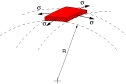
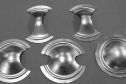
FLC is an important parameter for forming simulations (FEA). Every material has its individual forming limit curve, which is normally determined according to Nakajima or Marciniak during deep-drawing tests on sheet metal specimens.
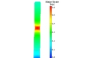
In this test setup, GOM’s ARAMIS 3D deformation measurement system records the deformation of different sheet metal blanks in a hydraulic testing machine with a spherical punch until failure. The result is the forming limit curve (FLC), which characterizes the material’s maximum formability and is evaluated by the GOM software according to ISO 12004.
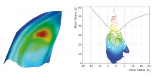
The determined forming limit curve is an essential input parameter for evaluating the forming process with the forming limit diagram during tool try-out. For example, the forming limits of the material might be exceeded at critical points, thus causing local neckings or cracks in the sheet metal. By using the FLC, overstretched areas with extreme material thickness reduction are identified so that the forming process can be optimized and part safety guaranteed.